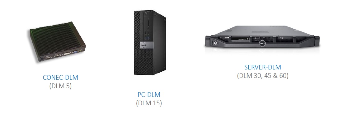
The THOR dynamic load balancing solution consists of a network device, a CT current clamp, a TCP2RS converter and a power analyser. The network device is installed into the customer’s server room and is connected via ethernet cable to the power analyser. The device can be rack mounted if necessary. Each charging station is connected to the customers’ network and is allocated an IP address. THOR connects to each charging station and manages the load on each station, dialing the charge up and down depending on the amount of available power in the building.
THOR uses a custom interface to dynamically load balance charging stations because the load balancing features available in OCPP 1.6 lack functionality. OCPP 1.6 network management systems do have some rudimentary load balancing capability but this only works on fixed limits because, in the absence of a power analyser, the OCPP server cannot tell how much power is available.
THOR shares out the available power between the charging stations and then reduces the power allocated to each charging station when the power limit is reached. The power limit is either a hard limit which reflects the maximum amount of power that should be available in the parking area or a dynamic limit which is dependent the maximum amount of power available to the building as a whole.
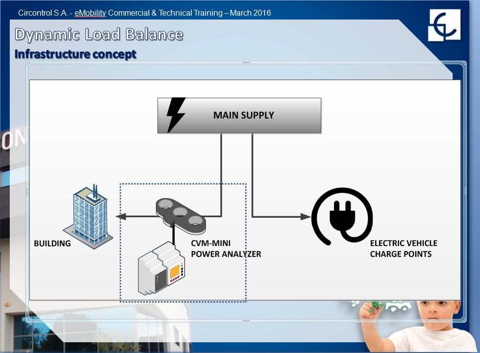
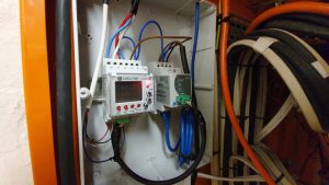
A current clamp is attached to the circuit and connected to a power analyser which is connected by network cable to a switch/router. The THOR network device and the charging stations are connected to the same switch. The power analyser measures spare capacity on the circuit and dynamically allocates the available power across the charging stations, regulating the charge on the cars up and down.
The switch can be connected to the customer network or a router with a 4G SIM card which is connected to the Charge Star network. The latter configuration is air-gapped so that there is no physical connection to the internal network and is suitable in situations where the charging station network management is being outsourced to a managed service provider.

- If the provider has opted to monitor the total consumption of the building and dynamically limit the power to the parking area, Thor will pause some of the charging sessions and queue up new charging sessions if the available power per charging station falls below 1.5 kW. THOR will restore charging sessions when the available power per active charging station is greater than 1.5 kW. The scenario will only occur if the building is using most of the available power.
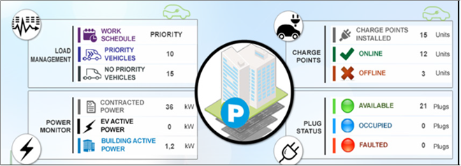
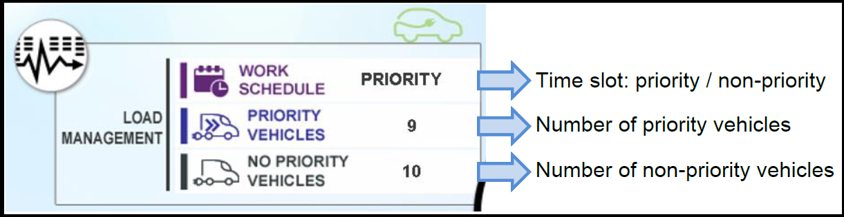
- Some Charging Stations can be designated VIP or priority charging stations. VIP charging stations will operate at full power all the time within an established time slot. VIP charging stations are designed for drivers who have permanent designated paring bays in the car park such as UPark Permanent Reserve Customers.
- THOR detects when cars stop charging and redistributes the power.
- All charging stations and the building analyser are ethernet enabled and are assigned fixed IP addresses.
- The THOR management and reporting portal is accessed via a HTTP server running on the THOR network device.
- THOR has an easy to understand point and click interface with a host of monitoring, management and reporting features.
- THOR can be configured so that existing charging sessions will continue and new charging sessions are paused if the network goes down or the PC goes off-line.
- The provider installs 10 charging stations rated to 7kW each in the car park.
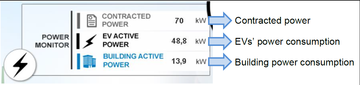
- The total demand for power if all stations are in use is 70 kW.
- The provider wants to limit the maximum power usage of all charging stations to 50 kW.
- The provider sets a hard limit of 50 kW for the parking area on the assumption that 50 kW is always available for the parking area. This means that not all charging stations can deliver full power at the same time.
- Driver 8 enters the car park. Seven stations are already in use drawing 7 kW each, a total of 49 kW out of an available 50 kW.
- Driver 8 parks at station 8 and plugs in.
- THOR shares out the available 50 kW over 8 stations.
- Each station now gets 6.25 kW.
- An hour later drivers 9 and 10 enter the car park and park at stations 9 and 10.
- The drivers plug in.
- THOR shares out the available 50 kW over 10 stations.
- Each station now gets 5 kW.
- Drives 1, 2 and 3 finish charging. THOR shares the power out over the other seven stations which now receive 7 kW each.
The provider has the option of monitoring the total consumption of the building and limiting the power supplied to the parking area to the available power which is the difference between the amount of power being used by the building and the building limit.
For example, if the building is limited to 100 kW and the building is using 60 kW then THOR limits the power available for charging to 40 kW and the 40 kW is shared between the charging stations as described in the scenario above. THOR will reduce the power available to each active charging station when driver six starts charging and demand exceeds 40 kW.